Resistance

The electrical resistance of a circuit component or device is defined as the ratio of the voltage applied to the electric current whichflows through it:


If the resistance is constant over a considerable range of voltage, then Ohm's law, I = V/R, can be used to predict the behavior of the material. Although the definition above involves DC current and voltage, the same definition holds for the AC application of resistors.

Whether or not a material obeys Ohm's law, its resistance can be described in terms of its bulk resistivity. The resistivity, and thus the resistance, is temperature dependent. Over sizable ranges of temperature, this temperature dependence can be predicted from a temperature coefficient of resistance.

Conductors and insulatorsResistor combinationsNon-ohmic resistance: the electric pickle
AC behavior of resistorCommon carbon resistors
Index

DC Circuits
 
HyperPhysics*****Electricity and magnetismR Nave
Go Back


Resistivity and Conductivity

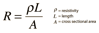
The electrical resistance of a wire would be expected to be greater for a longer wire, less for a wire of larger cross sectional area, and would be expected to depend upon the material out of which the wire is made. Experimentally, the dependence upon these properties is a straightforward one for a wide range of conditions, and the resistance of a wire can be expressed as


The factor in the resistance which takes into account the nature of the material is the resistivity . Although it is temperature dependent, it can be used at a given temperature to calculate the resistance of a wire of given geometry.

The inverse of resistivity is called conductivity. There are contexts where the use of conductivity is more convenient.

Electrical conductivity = σ = 1/ρ

CalculationTable of resistivitiesCommon wire gauges
Microscopic view of resistivity
Index
 
HyperPhysics*****Electricity and magnetismR Nave
Go Back


Resistor Combinations

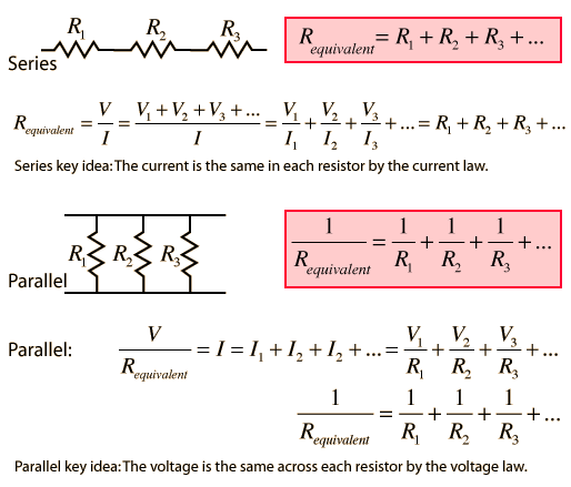
The combination rules for any number of resistors in series or parallel can be derived with the use of Ohm's Law, the voltage law, and the current law.


Comparison example
Index

DC Circuits
 
HyperPhysics*****Electricity and magnetismR Nave
Go Back


Resistivity Calculation

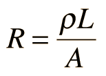
The electrical resistance of a wire would be expected to be greater for a longer wire, less for a wire of larger cross sectional area, and would be expected to depend upon the material out of which the wire is made (resistivity). Experimentally, the dependence upon these properties is a straightforward one for a wide range of conditions, and the resistance of a wire can be expressed as


Resistance = resistivity x length/area
For a wire of length L = m = ft
and area A = cm2
corresponding to radius r = cm
and diameter inches for common wire gauge comparison
with resistivity = ρ = x 10^ ohm meters
will have resistance R = ohms.

Enter data and then click on the quantity you wish to calculate in the active formula above. Unspecified parameters will default to values typical of 10 meters of #12 copper wire. Upon changes, the values will not be forced to be consistent until you click on the quantity you wish to calculate.

Commonly used U.S. wire gauges
for copper wire.
AWG
Diameter
(inches)
Typical use
10
0.1019
Electric range
12
0.0808
Household circuit
14
0.0640
Switch leads
Standard wire gauges
Resistivities of some metals
in ohm-m(x 10-8) at 20°C.
Aluminum
2.65
Gold
2.24
Copper
1.724
Silver
1.59
Iron
9.71
Platinum
10.6
Nichrome
100
Tungsten
5.65
Table of resistivities

The factor in the resistance which takes into account the nature of the material is the resistivity . Although it is temperature dependent, it can be used at a given temperature to calculate the resistance of a wire of given geometry.

DiscussionTable of resistivitiesCommon wire gauges
Index
 
HyperPhysics*****Electricity and magnetismR Nave
Go Back